




How does the power factor change in an LCR circuit?
 Aug 08, 2025|
 How does the power factor change in an LCR circuit?
As an LCR supplier, I've had the privilege of witnessing firsthand the intricate dance of electrical components within LCR circuits. One of the most fascinating aspects of these circuits is the power factor, a parameter that plays a crucial role in determining the efficiency of electrical power utilization. In this blog post, I'll delve into the factors that influence the power factor in an LCR circuit and explore how it changes under different conditions.
Understanding the Power Factor
Before we dive into the details of how the power factor changes in an LCR circuit, let's first understand what the power factor is. In an AC circuit, the power factor is defined as the ratio of the real power (P) to the apparent power (S). Real power is the power that is actually consumed by the circuit and is measured in watts (W), while apparent power is the product of the voltage (V) and current (I) in the circuit and is measured in volt-amperes (VA).
The power factor (PF) is given by the formula:
[ PF = \frac{P}{S} ]
A power factor of 1 (or 100%) indicates that all the electrical power supplied to the circuit is being used effectively, while a power factor less than 1 means that some of the power is being wasted in the form of reactive power. Reactive power is the power that oscillates between the source and the load without being consumed and is measured in volt-amperes reactive (VAR).
The Role of Inductance and Capacitance in an LCR Circuit
An LCR circuit consists of three main components: an inductor (L), a capacitor (C), and a resistor (R). The inductor stores energy in its magnetic field, while the capacitor stores energy in its electric field. The resistor dissipates energy in the form of heat.
In an AC circuit, the inductance and capacitance introduce a phase difference between the voltage and current. The inductive reactance ((X_L)) and capacitive reactance ((X_C)) are given by the formulas:
[ X_L = 2\pi fL ]
[ X_C = \frac{1}{2\pi fC} ]
where (f) is the frequency of the AC signal, (L) is the inductance in henries (H), and (C) is the capacitance in farads (F).
The impedance ((Z)) of the LCR circuit is given by the formula:
[ Z = \sqrt{R^2 + (X_L - X_C)^2} ]
The phase angle ((\theta)) between the voltage and current is given by the formula:
[ \theta = \arctan\left(\frac{X_L - X_C}{R}\right) ]
The power factor is related to the phase angle by the formula:
[ PF = \cos(\theta) ]
How the Power Factor Changes with Frequency
One of the key factors that influence the power factor in an LCR circuit is the frequency of the AC signal. At low frequencies, the inductive reactance ((X_L)) is small, while the capacitive reactance ((X_C)) is large. As a result, the circuit behaves more like a capacitive circuit, and the current leads the voltage. The power factor is less than 1, and the circuit consumes reactive power.
As the frequency increases, the inductive reactance ((X_L)) increases, while the capacitive reactance ((X_C)) decreases. At a certain frequency, called the resonant frequency ((f_0)), the inductive reactance ((X_L)) is equal to the capacitive reactance ((X_C)), and the impedance of the circuit is equal to the resistance ((R)). At resonance, the phase angle ((\theta)) is zero, and the power factor is equal to 1. This means that all the electrical power supplied to the circuit is being used effectively, and there is no reactive power.
As the frequency continues to increase beyond the resonant frequency, the inductive reactance ((X_L)) becomes larger than the capacitive reactance ((X_C)), and the circuit behaves more like an inductive circuit. The current lags the voltage, and the power factor is less than 1 again. The circuit consumes reactive power, and some of the electrical power is being wasted.
Measuring the Power Factor in an LCR Circuit
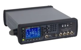
To measure the power factor in an LCR circuit, you can use an LCR meter. There are several high-quality LCR meters available in the market, such as the PM6304 Fluke LCR Meter, 4287A Agilent LCR Meter, 1 MHz - 3 GHz, and E4980A Agilent LCR Meter, 20 Hz - 2 MHz. These meters can accurately measure the inductance, capacitance, resistance, and power factor of an LCR circuit.
Improving the Power Factor in an LCR Circuit
In many applications, it is desirable to improve the power factor of an LCR circuit to reduce the amount of reactive power and increase the efficiency of electrical power utilization. One way to improve the power factor is to add a capacitor in parallel with the inductive load. The capacitor provides a leading current that cancels out the lagging current of the inductive load, thereby reducing the phase difference between the voltage and current and increasing the power factor.
Another way to improve the power factor is to use a power factor correction (PFC) circuit. A PFC circuit is an electronic circuit that adjusts the current waveform to match the voltage waveform, thereby improving the power factor. PFC circuits are commonly used in power supplies, motors, and other electrical equipment to reduce the amount of reactive power and improve the efficiency of electrical power utilization.
Conclusion
The power factor is an important parameter in an LCR circuit that determines the efficiency of electrical power utilization. The power factor changes with frequency and is influenced by the inductance, capacitance, and resistance of the circuit. At resonance, the power factor is equal to 1, and all the electrical power supplied to the circuit is being used effectively. To measure the power factor in an LCR circuit, you can use an LCR meter, such as the PM6304 Fluke LCR Meter, 4287A Agilent LCR Meter, 1 MHz - 3 GHz, or E4980A Agilent LCR Meter, 20 Hz - 2 MHz.

If you're interested in improving the power factor of your LCR circuits or need high-quality LCR components and meters, we're here to help. Contact us to discuss your specific requirements and explore how we can provide the solutions you need.
References
- Electric Circuits (9th Edition) by James W. Nilsson and Susan A. Riedel
- Fundamentals of Electric Circuits (5th Edition) by Charles K. Alexander and Matthew N. O. Sadiku