




How to analyze a parallel LCR circuit?
 Jan 09, 2026|
 An LCR circuit, also known as an RLC circuit, is a fundamental electrical circuit that combines inductors (L), capacitors (C), and resistors (R). When these components are connected in parallel, it forms a parallel LCR circuit. Analyzing this type of circuit is crucial for understanding its behavior, such as resonance, impedance, and current distribution. As an LCR supplier, I'm here to guide you through the process of analyzing a parallel LCR circuit.

Understanding the Basics of a Parallel LCR Circuit
A parallel LCR circuit consists of a resistor, an inductor, and a capacitor all connected in parallel across a voltage source. Each component has its own impedance, which affects the overall behavior of the circuit. The impedance of a resistor (R) is a real value and is equal to its resistance. The impedance of an inductor (L) is given by (Z_L = jωL), where (j) is the imaginary unit, (\omega) is the angular frequency ((\omega = 2\pi f)), and (L) is the inductance. The impedance of a capacitor (C) is (Z_C=\frac{1}{j\omega C}).
Calculating the Total Impedance of the Parallel LCR Circuit
The total impedance ((Z_{total})) of a parallel LCR circuit can be calculated using the formula for parallel impedances. The reciprocal of the total impedance is equal to the sum of the reciprocals of the individual impedances:
(\frac{1}{Z_{total}}=\frac{1}{R}+\frac{1}{j\omega L}+j\omega C)
To simplify this expression, we can combine the terms:
(\frac{1}{Z_{total}}=\frac{1}{R}+j(\omega C - \frac{1}{\omega L}))
The magnitude of the total impedance is given by:
(\vert Z_{total}\vert=\frac{1}{\sqrt{(\frac{1}{R})^2+(\omega C - \frac{1}{\omega L})^2}})
The phase angle ((\theta)) of the total impedance is:
(\theta = -\arctan\left(\frac{\omega C - \frac{1}{\omega L}}{\frac{1}{R}}\right))
Resonance in a Parallel LCR Circuit
Resonance occurs in a parallel LCR circuit when the inductive reactance ((X_L=\omega L)) is equal to the capacitive reactance ((X_C = \frac{1}{\omega C})). At resonance, the impedance of the circuit is at its maximum value, and the current flowing through the circuit is at its minimum. The resonant frequency ((f_0)) can be calculated using the formula:
(\omega_0=\frac{1}{\sqrt{LC}})
(f_0=\frac{1}{2\pi\sqrt{LC}})
At resonance, the circuit behaves like a purely resistive circuit because the inductive and capacitive reactances cancel each other out.
Analyzing the Current Distribution in a Parallel LCR Circuit
In a parallel LCR circuit, the voltage across each component is the same. However, the current flowing through each component is different. The current through the resistor ((I_R)) is given by (I_R=\frac{V}{R}), where (V) is the voltage across the circuit. The current through the inductor ((I_L)) is (I_L=\frac{V}{j\omega L}), and the current through the capacitor ((I_C)) is (I_C = j\omega CV).
The total current ((I_{total})) flowing through the circuit can be calculated using the principle of superposition:
(I_{total}=I_R + I_L+I_C)
Since the currents through the inductor and capacitor are out of phase with each other, they can cancel each other out at resonance.
Measuring and Verifying the Circuit Parameters
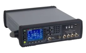
To accurately analyze a parallel LCR circuit, it's essential to measure the values of the components and the circuit's electrical characteristics. This is where high-quality LCR meters come in handy. As an LCR supplier, we offer a range of top-of-the-line LCR meters, such as the E4980A Agilent LCR Meter, 20 Hz - 2 MHz, the PM6304 Fluke LCR Meter, and the E4982A Agilent LCR Meter, 1 MHz To 300 MHz / 500 MHz / 1 GHz / 3 GHz. These meters can accurately measure the resistance, inductance, and capacitance of the components, as well as the impedance and phase angle of the circuit.
Practical Applications of Parallel LCR Circuits
Parallel LCR circuits have numerous practical applications in electrical and electronic systems. They are commonly used in filter circuits to block or pass specific frequencies. For example, a parallel LCR circuit can be used as a band-stop filter to reject a narrow range of frequencies around the resonant frequency. They are also used in resonant circuits for oscillators, Radio - Frequency (RF) circuits, and power factor correction circuits.
Considerations for Designing and Analyzing Parallel LCR Circuits
When designing and analyzing parallel LCR circuits, several factors need to be considered. The quality factor (Q) of the circuit is an important parameter that indicates the selectivity and energy storage capabilities of the circuit. A high Q factor means a narrow bandwidth and a more selective circuit. The tolerance of the components also affects the performance of the circuit. Components with high tolerances can introduce errors in the circuit's behavior.
Conclusion
Analyzing a parallel LCR circuit involves understanding its basic principles, calculating the total impedance, identifying the resonant frequency, and analyzing the current distribution. By using high-quality LCR meters and considering the practical applications and design considerations, you can accurately analyze and design parallel LCR circuits for various electrical and electronic systems.
If you're in the market for LCR meters or other related components, we're here to help. As an LCR supplier, we can provide you with the highest quality products and the technical support you need. Whether you're a professional engineer working on complex projects or a hobbyist exploring the world of electronics, we can assist you in finding the right solutions for your needs. Feel free to contact us for more information or to discuss your procurement requirements.
References
- Boylestad, R. L., & Nashelsky, L. (2012). Electronic Devices and Circuit Theory. Pearson.
- Nilsson, J. W., & Riedel, S. A. (2014). Electric Circuits. Pearson.