




How to analyze a series LCR circuit?
 Dec 26, 2025|
 How to Analyze a Series LCR Circuit
A series LCR circuit, also known as a resonant circuit, is a fundamental electrical circuit that consists of an inductor (L), a capacitor (C), and a resistor (R) connected in series. This circuit is widely used in various applications, such as radio receivers, filters, and oscillators. Understanding how to analyze a series LCR circuit is crucial for electrical engineers, hobbyists, and anyone interested in electronics. As a trusted LCR supplier, I am here to share with you some detailed insights into analyzing this type of circuit.
Basic Components and Their Properties
Let's first briefly review the basic components of a series LCR circuit.
-
Resistor (R): A resistor opposes the flow of electric current. According to Ohm's law, the voltage across a resistor (V_R = IR), where (I) is the current flowing through the resistor and (R) is the resistance value. The power dissipated in a resistor is given by (P = I^{2}R). Resistors are used to control the current and voltage in a circuit and to dissipate energy in the form of heat.
-
Inductor (L): An inductor stores energy in its magnetic field. The voltage across an inductor is given by (V_L = L\frac{di}{dt}), where (L) is the inductance and (\frac{di}{dt}) is the rate of change of current. Inductors oppose changes in current. In an AC circuit, the inductive reactance (X_L=\omega L = 2\pi fL), where (\omega) is the angular frequency and (f) is the frequency of the alternating current.
-
Capacitor (C): A capacitor stores energy in its electric field. The current through a capacitor is (i = C\frac{dv}{dt}), where (C) is the capacitance and (\frac{dv}{dt}) is the rate of change of voltage. The capacitive reactance (X_C=\frac{1}{\omega C}=\frac{1}{2\pi fC}). Capacitors oppose changes in voltage in a circuit.
Impedance of a Series LCR Circuit
The impedance (Z) of a series LCR circuit is a measure of the total opposition to the flow of alternating current. It is a complex quantity and can be calculated using the formula (Z=\sqrt{R^{2}+(X_L - X_C)^{2}}). The phase angle (\varphi) between the current and the voltage in the circuit is given by (\tan\varphi=\frac{X_L - X_C}{R}).
When (X_L=X_C), the circuit is in resonance. At resonance, the impedance (Z = R) (the minimum value), and the current in the circuit reaches its maximum value (I=\frac{V}{R}), where (V) is the applied voltage. The resonant frequency (f_0) of a series LCR circuit is given by (f_0=\frac{1}{2\pi\sqrt{LC}}).
Analyzing the Voltage and Current in a Series LCR Circuit
To analyze the voltage and current in a series LCR circuit, we can use phasor diagrams. A phasor is a rotating vector that represents the magnitude and phase of an alternating quantity.
The current (I) is the same through all the components in a series circuit. The voltage across the resistor (V_R) is in phase with the current. The voltage across the inductor (V_L) leads the current by 90 degrees, and the voltage across the capacitor (V_C) lags the current by 90 degrees.
The total voltage (V) across the series LCR circuit can be found using the phasor addition: (V = \sqrt{V_R^{2}+(V_L - V_C)^{2}}).
We can also analyze the power in a series LCR circuit. The average power (P) dissipated in the circuit is given by (P = VI\cos\varphi), where (\cos\varphi) is the power factor. At resonance, (\varphi = 0) and the power factor (\cos\varphi = 1), which means all the power is dissipated in the resistor.
Using LCR Meters for Analysis
To accurately measure the parameters of an LCR circuit, we can use LCR meters. As an LCR supplier, I can introduce some popular LCR meters in the market.
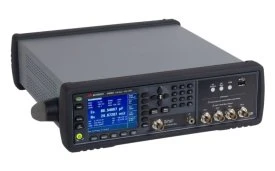

The PM6304 Fluke LCR Meter is a highly reliable tool. It offers high - precision measurements and can be used to measure the inductance, capacitance, and resistance of components in a series LCR circuit. It provides accurate readings even in complex electrical environments.
The E4980A Agilent LCR Meter, 20 Hz - 2 MHz has a wide frequency range, which is very useful for analyzing series LCR circuits under different frequency conditions. It can help us to study the behavior of the circuit at various frequencies and find the resonant frequency more precisely.
The 4263B Agilent LCR Meter, 100 Hz To 100 KHz is another great option for analyzing LCR circuits within its frequency range. It provides stable and accurate measurements, which are essential for circuit design and troubleshooting.
Step - by - Step Analysis Process
- Determine the Circuit Parameters: First, identify the values of the resistor (R), inductor (L), and capacitor (C) in the series LCR circuit. If these values are not known, you can use an LCR meter to measure them.
- Calculate the Reactances: Calculate the inductive reactance (X_L = 2\pi fL) and the capacitive reactance (X_C=\frac{1}{2\pi fC}) at a given frequency (f) of the applied AC voltage.
- Calculate the Impedance: Use the formula (Z=\sqrt{R^{2}+(X_L - X_C)^{2}}) to calculate the impedance of the circuit.
- Find the Current: If the applied voltage (V) is known, calculate the current (I=\frac{V}{Z}) using Ohm's law for AC circuits.
- Determine the Voltages across Components: Calculate the voltages across the resistor (V_R = IR), the inductor (V_L = IX_L), and the capacitor (V_C = IX_C).
- Analyze the Phase Angle: Calculate the phase angle (\varphi=\tan^{- 1}\left(\frac{X_L - X_C}{R}\right)) to understand the phase relationship between the voltage and the current.
- Check for Resonance: Calculate the resonant frequency (f_0=\frac{1}{2\pi\sqrt{LC}}). At resonance, the circuit shows special characteristics, such as maximum current and minimum impedance.
Conclusion
Analyzing a series LCR circuit is a fundamental skill in electrical engineering and electronics. By understanding the properties of the components, calculating the impedance, voltage, current, and phase angle, and using appropriate LCR meters, we can gain a deep understanding of the behavior of the circuit. Whether you are designing a new circuit, troubleshooting an existing one, or simply learning about electronics, the analysis of series LCR circuits is an essential part.
If you are interested in purchasing high - quality LCR meters or other related components for your analysis needs, please feel free to contact us for procurement and negotiation. We are committed to providing you with the best products and services to meet your requirements.
References
- Boylestad, Robert L., and Louis Nashelsky. "Electronic Devices and Circuit Theory." Pearson Education, 2018.
- Alexander, Charles K., and Matthew N. O. Sadiku. "Fundamentals of Electric Circuits." McGraw - Hill Education, 2019.