




How to measure the parameters of an LCR circuit?
 Aug 04, 2025|
 In the field of electronics, LCR circuits, which consist of inductors (L), capacitors (C), and resistors (R), play a crucial role. These circuits are fundamental in various applications, from simple filter circuits to complex communication systems. Measuring the parameters of an LCR circuit accurately is essential for circuit design, troubleshooting, and quality control. As an LCR supplier, I am well - versed in the methods and tools required for these measurements.
Understanding LCR Circuit Parameters
Before delving into the measurement techniques, it's important to understand the key parameters of an LCR circuit. Resistance (R) is a measure of the opposition to the flow of electric current in a circuit. It is measured in ohms (Ω). Inductance (L) is the property of an inductor that opposes changes in current flow. It is measured in henries (H). Capacitance (C) is the ability of a capacitor to store electrical energy in an electric field. It is measured in farads (F).

Other important parameters include impedance (Z), which is the total opposition to the flow of alternating current (AC) in a circuit, and phase angle (φ), which describes the relationship between the voltage and current in an AC circuit.
Measurement Methods
Bridge Methods
One of the traditional methods for measuring LCR parameters is the bridge method. The Wheatstone bridge is commonly used for measuring resistance. It works on the principle of comparing an unknown resistance with known resistances. When the bridge is balanced, the ratio of the known resistances is equal to the ratio of the unknown resistance to a variable resistance.
For measuring inductance, the Maxwell - Wien bridge and the Hay bridge are commonly used. These bridges compare the unknown inductance with a known capacitance and resistance. Similarly, the Schering bridge is used for measuring capacitance. Bridge methods are known for their high accuracy, but they can be time - consuming and require careful balancing.
Resonance Methods
Resonance methods are based on the principle of resonance in an LCR circuit. When an LCR circuit is in resonance, the inductive reactance (XL) is equal to the capacitive reactance (XC). At resonance, the impedance of the circuit is minimum and is equal to the resistance (R).
To measure inductance using the resonance method, a variable frequency AC source is applied to the LCR circuit. The frequency is adjusted until resonance is achieved. The inductance can then be calculated using the resonance frequency formula (f_0=\frac{1}{2\pi\sqrt{LC}}), where (f_0) is the resonance frequency.
Resonance methods are relatively simple and can provide accurate results, but they are limited to measuring at the resonance frequency.
Digital LCR Meters
Digital LCR meters are the most commonly used tools for measuring LCR parameters today. These meters are capable of measuring resistance, inductance, capacitance, impedance, and phase angle directly. They work by applying an AC signal to the device under test (DUT) and measuring the resulting voltage and current.
Digital LCR meters offer several advantages over traditional methods. They are fast, easy to use, and can provide multiple parameter measurements simultaneously. They also have a wide range of measurement frequencies, allowing for measurements at different frequencies.
Choosing the Right LCR Meter
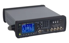
As an LCR supplier, I offer a variety of LCR meters to meet different measurement needs. Here are some popular models:
- 4284A Agilent Precision LCR Meter, 20 Hz To 1 MHz: This meter is known for its high precision and wide frequency range. It is suitable for a variety of applications, including component testing, research, and development.
- E4980A Agilent LCR Meter, 20 Hz - 2 MHz: With a higher frequency range than the 4284A, the E4980A is ideal for measuring high - frequency components and circuits. It offers high accuracy and fast measurement speed.
- 4285A Agilent LCR Meter, 75 KHz - 30 MHz: This meter is designed for high - frequency measurements. It is suitable for applications such as RF component testing and communication systems.
When choosing an LCR meter, several factors should be considered. These include the required measurement accuracy, the frequency range of the measurements, the number of parameters to be measured, and the budget.
Measurement Considerations
When measuring LCR parameters, there are several factors that can affect the accuracy of the measurements. These include:
- Parasitic Effects: Parasitic capacitance and inductance in the test setup can affect the measured values. To minimize these effects, proper shielding and grounding techniques should be used.
- Temperature: The values of LCR components can change with temperature. It is important to measure the components at a stable temperature or to use temperature - compensated measurement techniques.
- Frequency: The values of LCR components can vary with frequency. It is important to measure the components at the frequency of operation in the actual circuit.
Contact for Purchase and Consultation
If you are in need of accurate LCR parameter measurements for your projects, whether it's for research, development, or production, having the right LCR meter is crucial. As an experienced LCR supplier, I can offer you high - quality LCR meters that meet your specific requirements.
Whether you are looking for a meter with a wide frequency range, high precision, or fast measurement speed, I have the solution for you. If you have any questions about the measurement methods, the choice of LCR meters, or need further technical support, please feel free to contact me. I am more than happy to assist you in making the right decision for your LCR measurement needs. Let's start a conversation and find the best LCR measurement solution for your applications.
References
- "Electrical Measurements" by A. K. Sawhney
- "Electronic Instrumentation and Measurement Techniques" by David A. Bell
- Manufacturer's manuals for 4284A Agilent Precision LCR Meter, 20 Hz To 1 MHz, E4980A Agilent LCR Meter, 20 Hz - 2 MHz, and 4285A Agilent LCR Meter, 75 KHz - 30 MHz