




What is the role of LCR circuits in radio frequency applications?
 Jan 15, 2026|
 LCR circuits, which consist of inductors (L), capacitors (C), and resistors (R), play a pivotal and multifaceted role in radio frequency (RF) applications. As an LCR supplier, I have witnessed firsthand the critical importance of these circuits in various RF systems and technologies. In this blog post, I will delve into the diverse functions and significance of LCR circuits in the realm of radio frequency.
Resonance Phenomenon
One of the most fundamental and remarkable aspects of LCR circuits is their ability to exhibit resonance. At the resonant frequency, the inductive reactance (XL = 2πfL) and the capacitive reactance (XC = 1 / (2πfC)) are equal in magnitude but opposite in phase. This results in a net reactance of zero, and the impedance of the circuit is purely resistive. The resonant frequency (fr) of an LCR series circuit is given by the formula fr = 1 / (2π√(LC)).
In radio frequency applications, resonance is harnessed for a variety of purposes. For instance, in a radio receiver, an LCR circuit can be used as a tuned circuit. By adjusting the values of the inductor and capacitor, the circuit can be made to resonate at a specific radio frequency. This allows the receiver to selectively pick up signals at that particular frequency while rejecting signals at other frequencies. This is crucial for tuning into different radio stations. The selectivity of the tuned circuit depends on its quality factor (Q), which is defined as the ratio of the reactance at resonance to the resistance in the circuit (Q = XL / R = XC / R). A higher Q factor indicates a more selective circuit, able to pick out a narrow range of frequencies.
Filtering
LCR circuits are also widely used as filters in radio frequency applications. Filters are essential for separating different frequency components of a signal. There are several types of LCR filters, including low - pass filters, high - pass filters, band - pass filters, and band - stop filters.
A low - pass filter allows low - frequency signals to pass through while attenuating high - frequency signals. In an LCR low - pass filter, the inductor is typically placed in series with the input and the capacitor is connected in parallel to the output. As the frequency of the input signal increases, the inductive reactance increases, and the capacitive reactance decreases. This causes the high - frequency components to be blocked or attenuated.
Conversely, a high - pass filter allows high - frequency signals to pass and blocks low - frequency signals. In this case, the capacitor is placed in series with the input, and the inductor is connected in parallel to the output. As the frequency rises, the capacitive reactance decreases, allowing high - frequency components to pass through, while the high inductive reactance blocks low - frequency signals.
Band - pass filters are used to allow a specific range of frequencies to pass through while rejecting frequencies outside this range. They are commonly used in radio receivers to select a particular channel or frequency band. A band - pass filter can be constructed using an LCR circuit, and its center frequency and bandwidth can be adjusted by carefully choosing the values of the inductor, capacitor, and resistor.
Band - stop filters, on the other hand, block a specific range of frequencies while allowing frequencies outside this range to pass. They are useful for eliminating interference or unwanted signals at a particular frequency band.
Impedance Matching
In radio frequency systems, impedance matching is crucial for efficient power transfer between different components. Mismatched impedance can lead to signal reflections, which result in power loss and distortion. LCR circuits are often used for impedance matching purposes.
For example, a transformer - like structure can be created using an LCR circuit to match the impedance of a source to the impedance of a load. By properly selecting the values of the inductor and capacitor, the impedance of the LCR circuit can be adjusted to match either the source or the load impedance. This ensures that maximum power is transferred from the source to the load, improving the overall efficiency of the radio frequency system.
Oscillation
LCR circuits can also be used to generate oscillations at radio frequencies. An oscillator is a circuit that produces a continuous, periodic waveform without the need for an external input signal. In an LCR oscillator circuit, energy is continuously exchanged between the inductor and the capacitor, creating an alternating current.
One common type of LCR oscillator is the Colpitts oscillator. It consists of an LCR tank circuit (the combination of an inductor and a capacitor) and an amplifier. The tank circuit provides the feedback signal necessary for sustained oscillations, and the amplifier boosts the signal to maintain its amplitude. Oscillators are essential in radio transmitters to generate the carrier waves that carry the information (such as audio or data) over the airwaves.
Testing and Measurement with LCR Meters
As an LCR supplier, we understand the importance of accurate testing and measurement of LCR components. There are several high - quality LCR meters available in the market that can precisely measure the values of inductors, capacitors, and resistors. For example, the E4980AL Agilent Precision LCR Meter 20 Hz To 300 KHz / 500 KHz / 1 MHz offers a wide frequency range and high precision measurements. This meter is suitable for a variety of applications, including research and development, production testing, and quality control of LCR components.
Another popular option is the 4284A Agilent Precision LCR Meter, 20 Hz To 1 MHz. It provides accurate measurements of impedance, capacitance, and inductance over a broad frequency spectrum. This meter is often used in the design and testing of RF circuits and components.
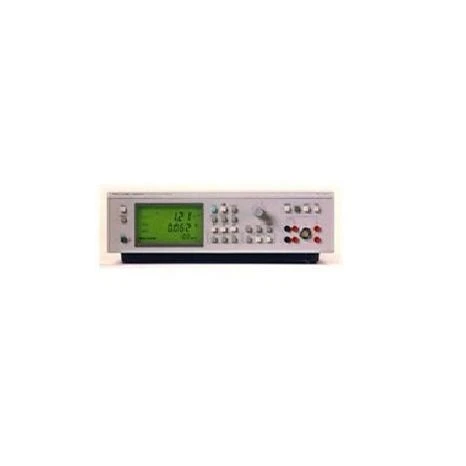

The PM6306 Fluke LCR Meter is also a reliable choice for measuring LCR values. It offers a user - friendly interface and high - performance measurement capabilities, making it suitable for both professional and educational purposes.
Conclusion
In conclusion, LCR circuits are the backbone of many radio frequency applications. Their ability to resonate, filter, match impedance, and generate oscillations is essential for the proper functioning of radio receivers, transmitters, and other RF systems. As an LCR supplier, we are committed to providing high - quality LCR components and solutions to meet the diverse needs of the radio frequency industry.
If you are interested in learning more about our LCR products or are looking to start a procurement discussion, we welcome you to reach out to us. Our team of experts is ready to assist you in finding the right LCR components for your specific RF applications.
References
- Hayt, W. H., & Kemmerly, J. E. (2001). Engineering Circuit Analysis. McGraw - Hill.
- Scherz, P., & Monk, S. (2008). Practical Electronics for Inventors. McGraw - Hill.
- Pozar, D. M. (2011). Microwave Engineering. Wiley.